Practical GD&T: Total Runout – Basic Concepts
Total runout is a somewhat more complex runout control, when compared to circular runout. It is sometimes described as ‘3D’ where circular runout is ‘2D’. This is a somewhat inaccurate analogy (see below), but it is true that total runout is generally more restrictive than circular runout (i.e. harder to pass to a given tolerance), and is also less straightforward to measure.
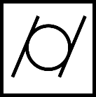
GD&T symbol
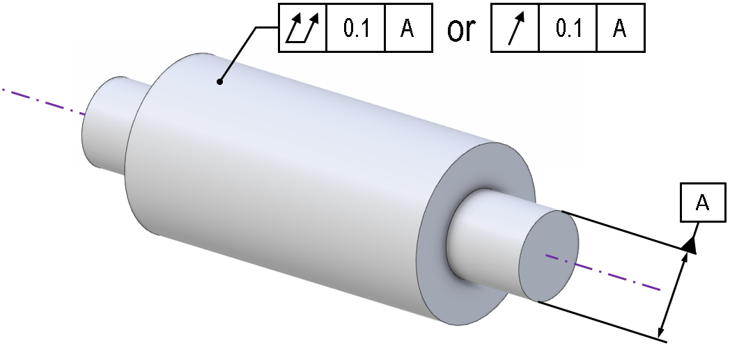
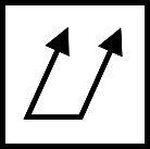
As with many of the GD&T controls, the graphical indication for total runout uses a ‘feature control frame’ or ‘tolerance frame’ (see <here> for details). A total runout control must always display the symbol (two parallel offset arrows connected at the base), a numerical value for the tolerance, and a datum reference for the axis of rotation.
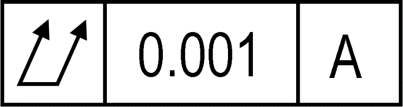
This is a minimum; a total runout control frame may have a secondary datum, tolerance modifiers such as a tangent plane modifier, or other modifiers such as a ‘between’ stipulation.
Drawing callout
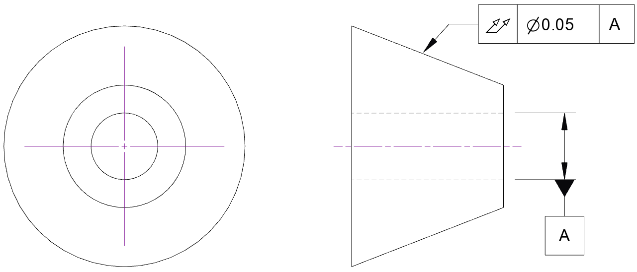
An example of a total runout control is shown for a simple geometry below
 C
C
Note that a circular runout control could just as easily have been used here, just by swapping the GD&T symbol, but this would change the meaning (see below). In this case though, with a total runout control, the tolerance zone is based on the entire surface, as the whole surface must be contained within a single, combined tolerance zone. That means in this case the tolerance zone would be formed by two concentric cones, constrained to have their axis of rotation aligned to datum axis ‘A’. The cones can be freely scaled, but the angle of the cones must be constrained to the nominal surface profile, and the difference in size between the two cones is fixed, defined by the numerical value given for the control frame tolerance.
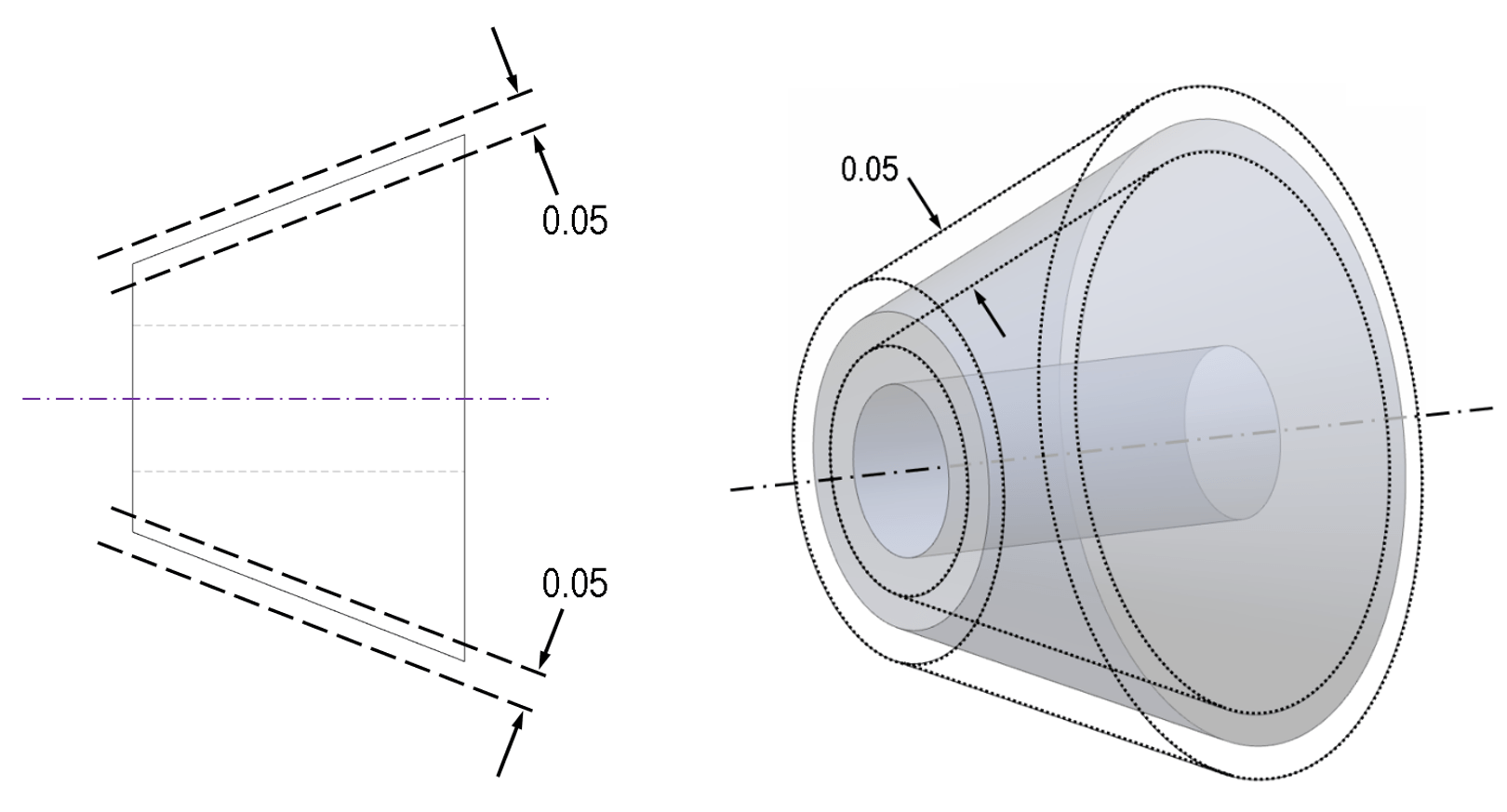
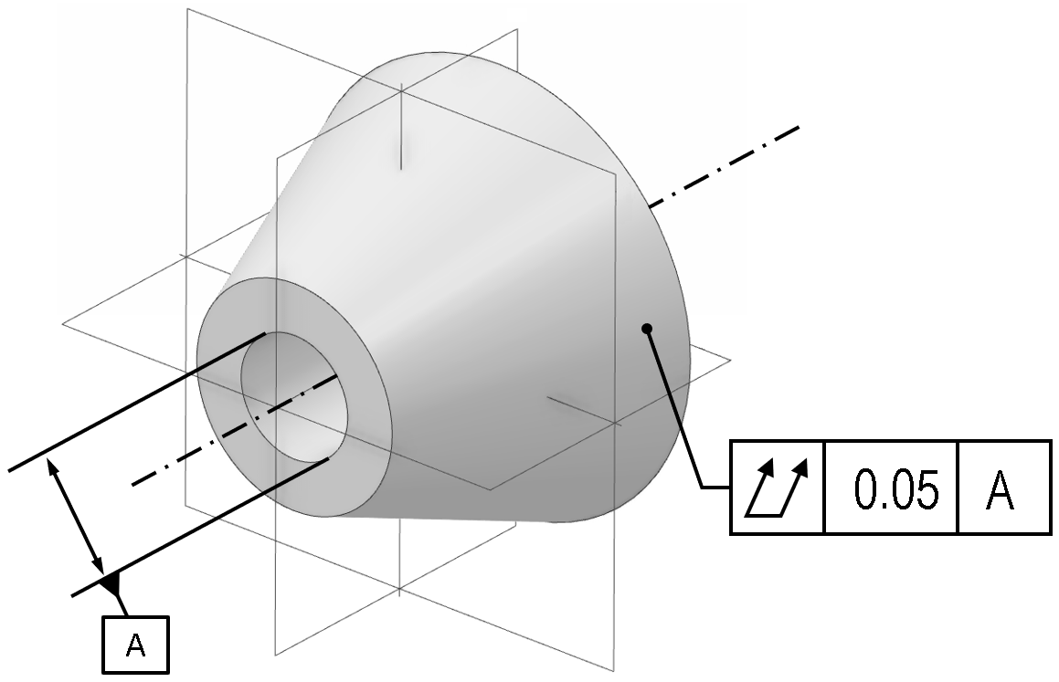
Above: the tolerance zone for this total runout constraint is two concentric cones
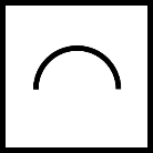
An important note here is that if the rotational profile is a complex freeform, then the tolerance zone can only be constructed and evaluated if the profile is fully mathematically described. This means that if a part features a freeform generatrix swept about an axis to form a rotationally symmetric profile, and if a callout for a total runout inspection of that surface is included, then the geometry of the nominal profile must be supplied to the inspector for suitable tolerance zone limits to be constructed. See the article on profile of a surface, where this same issue is encountered and discussed in more detail.
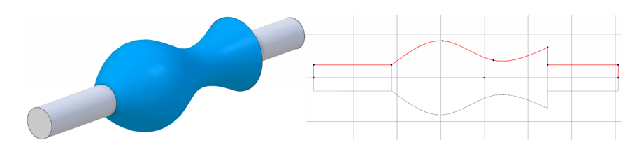
Above: a total runout control on this surface would require a numerical definition of the curved profile to be fed into the inspection process.
Circular runout or total runout?
It was noted in the introduction that labelling circular runout ‘2D’ and total runout ‘3D’ does not give an accurate picture of the relationship between the two.
To unpack the difference between circular runout and total runout, consider the cylindrical shaped element in the following image:
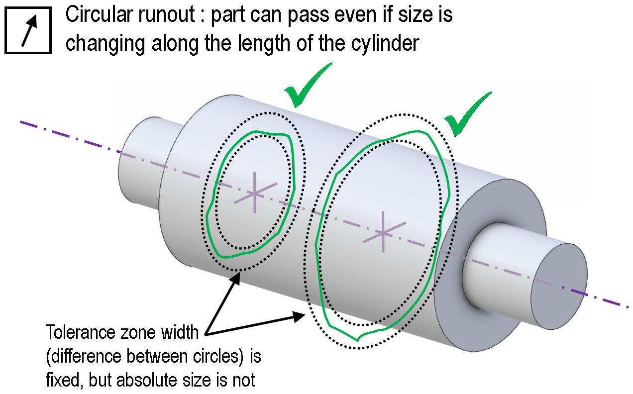
Either a circular runout or total runout control could be applied to the shape. But the meaning would be different;
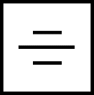
A circular runout control is illustrated below. The part will pass, as long as each individual check at any isolated location finds the profile to fit within two concentric circles (see circular runout). But the size of those circles is not constrained relative to any other cross-section. In other words, the tolerance zone is a series of independent 2D planes, each blind to the size of the circles in the other zones. This means a part can pass even if it has a form that is not cylindrical, as long as it is rotationally symmetric. So in this case, a gradual conical taper would not cause the check to fail.
A total runout control is more constrained. The tolerance zone is a 3D zone: two concentric cylinders in 3D space. So, unlike a circular runout check, the tolerance zone sizes at each location are effectively tied together. A part with a gradual conical taper would now fail.
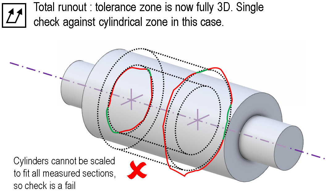
The obvious parallel is to roundness and cylindricity. As discussed in the article on cylindricity, a cylindrical surface can be round at all individual locations, without being cylindrical overall if it is bowed for instance. The difference between roundness/cylindricity and circular/total runout is twofold. Firstly, in a cylindricity or roundness check the tolerance zone is free to rotate, but with runout checks the tolerance zone must be centred on the axis. Secondly, runout can apply to a range of geometries other than cylinders; the shapes will always be round, but any rotationally symmetric profile is potentially valid for inspection.
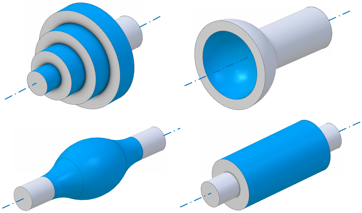
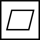
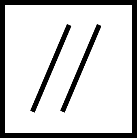
Applications of total runout
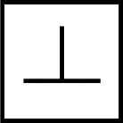
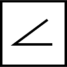
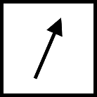
Total runout shares the same applicability as circular runout; any surface which is rotationally symmetric about an axis, be it cylindrical, conical, planar or a rotational freeform. The images below give more generic examples. Note the requirement though that the geometry must be possible to describe mathematically in order to inspect for total runout.
What GD&T standards apply to total runout?
ISO/ASME both cover runout, and both recognise the circular and total runout symbols. See ISO 1101 and ASME Y14.5. Both standards give plenty of good graphical illustrations to help understand the fine details.
Runout, roundness, and concentricity
Roundness / cylindricity, and concentricity/position might also be applicable to parts where total runout is controlled. For more on the relationship between these controls, see the article on circular runout.
Interested in fast and accurate measurement of precision components with an optical CMM? Try the OmniLux range of coordinate measuring machines.
Overview of GD&T
For an overview of GD&T including the other symbols, please see our practical guide.

Special case: Sphericity