Practical GD&T: Symmetry – Basic Concepts
In pure mathematical geometry, symmetry has a fundamental meaning which should be distinguished from the specific tolerance control used in engineering geometric dimensioning and tolerancing (GD&T). In GD&T the remit is more limited; the symmetry control in question normally describes a geometry which has at least one feature on it (not necessarily the entire part) that exhibits reflectional symmetry about a plane of symmetry than can be defined by some other reference.
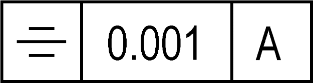
GD&T symbol
The basic control for symmetry uses a standard tolerance frame with, at the minimum, an accompanying tolerance value and a datum reference to define the plane of symmetry. Note that in the latest ASME standard the position control is used instead, so the control will look different (see below). Typically, a symmetry control is used for features with reflectional symmetry about a plane, while concentricity will be used for features with rotational symmetry about an axis.
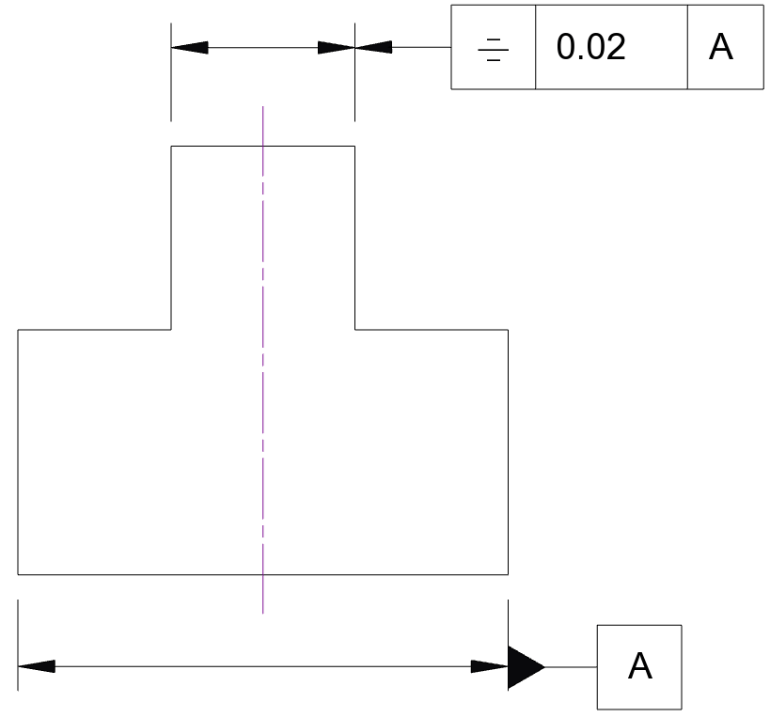
Drawing callout
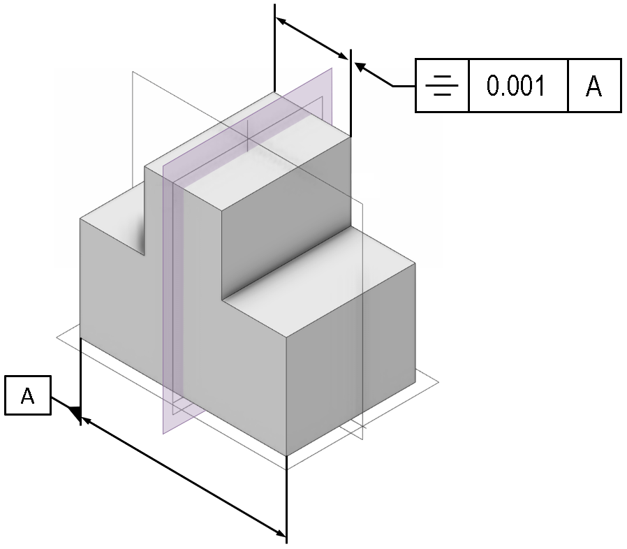
If using either the ISO or older ASME standards with the explicit symmetry control symbol (three parallel lines), the control will appear as shown below in a 2D engineering drawing or 3D CAD model:
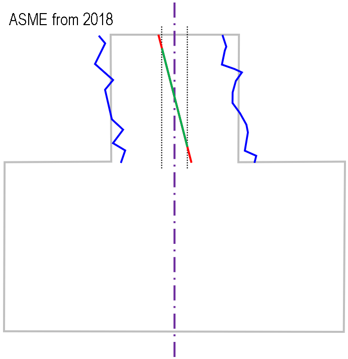
However, for the 2018 ASME standard, both concentricity and symmetry have been replaced with an extended use of the position control. Revisiting the above example part with the ASME position control to achieve the same thing as the symmetry control, the drawing might look like this:

Note that an additional datum constraint is now applied to give the part only one degree of freedom (one translation; no rotations).
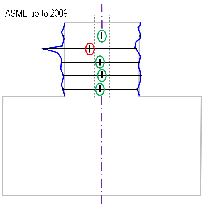
The interpretation of the check is slightly different in the different cases:
The older ASME standard is based on evaluating median points; every one of these measured median points must lie within the tolerance zone; as such, any single local outlier can cause the check to fail (compare the similar situation for concentricity with the older ASME standard). The ISO standard uses a similar concept, but describes the median surface (formed as a surface from the various medial points)
The newer ASME standard (using a position control) is based on a centre plane; to pass the check, this plane must lie within the tolerance zone over the extent of the measured region.
Note that, whichever standard is used, the evaluation of symmetry in this example requires the measurement of four faces – both the datum ‘A’ and the symmetry control are associated with a feature of size; this requires the two lower side-faces to be measured for the datum, and the two upper side-faces measured to check the symmetry is within tolerance.
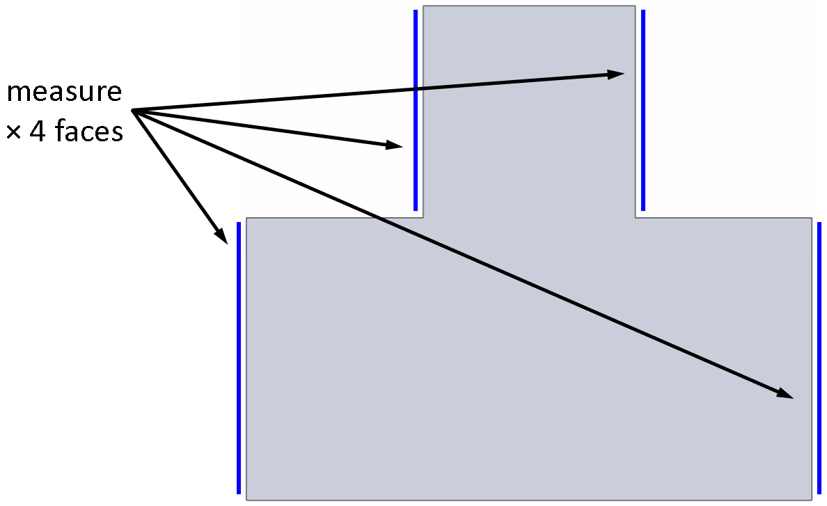
Many of the controls used in GD&T depend upon one or more datums (for instance, angularity or concentricity), and the way these datums are defined (and the measurement is prescribed) can often have an impact on the outcome of the control check. For the symmetry control, the datum is typically a virtual construction (e.g. a derived plane of symmetry constructed from measuring two opposing planar faces). For the symmetry check be repeatable, both the datum and the side faces must be measured in a way that is also clear and repeatable (e.g. using additional mark-up information such as datum targets and between-modifiers on the symmetry control).
Applications
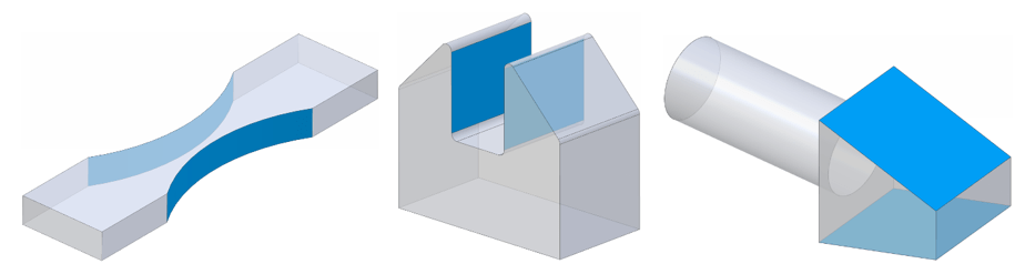
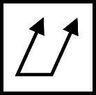
There is some ambiguity on when symmetry can apply. The (now retired) 2009 ASME standard Y14.5 suggested that the symmetry could reference “a datum axis or centre plane” implying rotational symmetry could be possible. The ISO standard refers only to a surface between two parallel planes, implying purely planar (reflective) symmetry. If using symmetry at all (and not position), it is advisable to reserve the symmetry control for planar cases. Examples of geometry where this control might apply are shown below; typically the examples given in the standards show parallel pairs of faces, but there is no strict reason why the control cannot apply to other forms.
One of the most common justifications for using concentricity and symmetry controls over some of the other GD&T callouts is cases where the physical balance of a part is important; i.e. effectively these controls are being used to establish the location of a centre of mass. This is strictly outside of the scope of GD&T which is geometric dimensioning and tolerancing, i.e. concerned purely with the shape of a part. And of course, if for instance a part has uneven density, then the geometry might be a poor indication of inertial properties. If centre of mass, moment of inertia etc are important, consider including these as specific functional tests. As a rule, where a functional test is accessible and low-cost consider using such tests rather than using a geometric check as an indirect surrogate for functional performance.
Standards
Very similar to the concentricity control, be aware that the version of the standard a drawing/model has been designed to is important. Symmetry was featured in the ASME Y14.5 standard up to and including the 2009 edition; the latest 2018 edition has removed the symmetry control (i.e. the GD&T control for symmetry is withdrawn, not the fundamental mathematical concept of symmetry). Under ISO 1101 the symmetry control is still valid using the symbol and behaviour described above. If in doubt, check carefully which version of which standard you, your customers and your suppliers are expecting to work to.
Remember, there is nothing to stop you mutually agreeing to use an older version of the standard, to make your own modifications to the standard, or your own internal standard, as long as there is good documentation and clear agreement within your supply chain.
Interested in fast and accurate measurement of precision components with an optical CMM? Try the OmniLux range of coordinate measuring machines.
Overview of GD&T
For an overview of GD&T including the other symbols, please see our practical guide.


Special case: Sphericity