Practical GD&T: Straightness Measurement – Basic Concepts
Straightness, from a GD&T perspective, is a control which requires either surfaces or axes to follow a straight line within a specified tolerance. This can apply in either two dimensions or three dimensions. A straightness control behaves slightly differently depending on exactly what feature it is applied to.
GD&T symbol
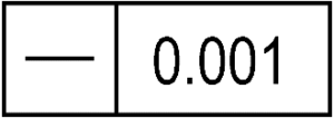
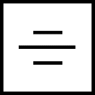
As with other surface form controls, a straightness control is denoted with a feature control frame, with a single straight line used for the symbol. A straightness tolerance must always include a numerical value for the tolerance zone separation.
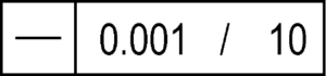
You may see straightness applied on a ‘per unit length’ basis as a zonal tolerance, as shown below. The additional number on the right is the size of the moving tolerance zone which now applies – in practice, this normally relaxes the overall control, compared to the same control without a ‘per unit length’ modifier. This may be applied alongside an additional (less stringent) tolerance for the overall feature – a standard tolerance which applies across the full length. Read more about using a ‘per unit’ feature control frame here.
Drawing callout
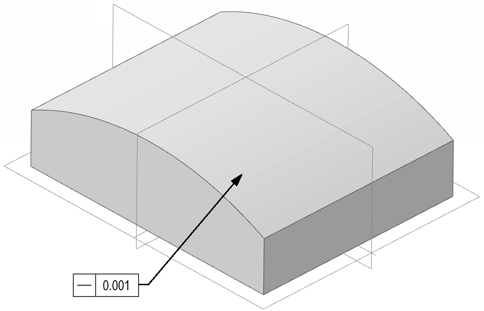
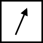
Straightness may be seen on 2D prints or 3D models, as a feature control frame (FCF):
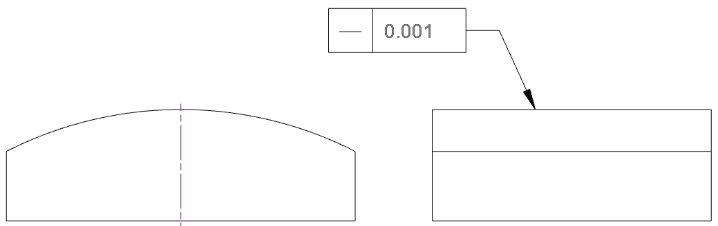
Note that where GD&T symbology is attached to the 3D CAD model, check to ensure that it is clear how the straightness is applied. In the image below the straightness can clearly only apply in one direction, but for a planar surface where straightness might apply in two directions the interpretation of the CAD model notation might be less obvious; ensure that the 2D engineering drawings clarify any ambiguity, or else some supplementary information is provided in the CAD model to indicate the direction of the straightness tolerance zone.
Straightness is unusual in that the shape of the tolerance zone can change, depending on the use of the straightness control. In the above example, the case is the simplest; straightness is measured following a 1D trace over the surface in 3D space, and the tolerance zone is a pair of parallel lines projected into a 2D plane normal to the surface, as illustrated below. The offset distance between the two parallel planes is equal to the numerical tolerance specified in the feature control frame.
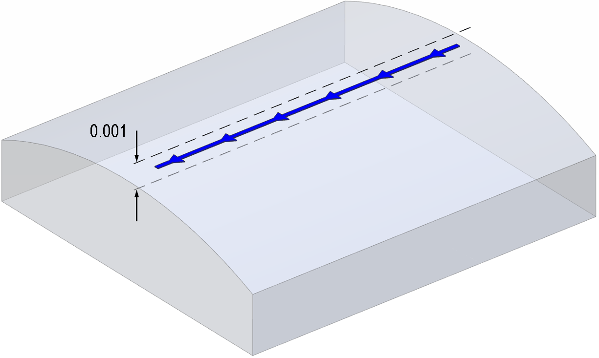
Note that the two lines can be both translated and rotated within that 2D plane in an attempt to fit the measured profile inside – the straightness control does not lock the inspection down relative to any other datums or features, apart from the requirement to remain within the 2D inspection plane.
If all points along this measured line now fall within those two bounding lines (purely within the 2D plane of measurement) then the part is a pass. If any point always deviates outside of the two lines, no matter how the lines are adjusted (keeping the fixed separation of course), then the part is a fail.
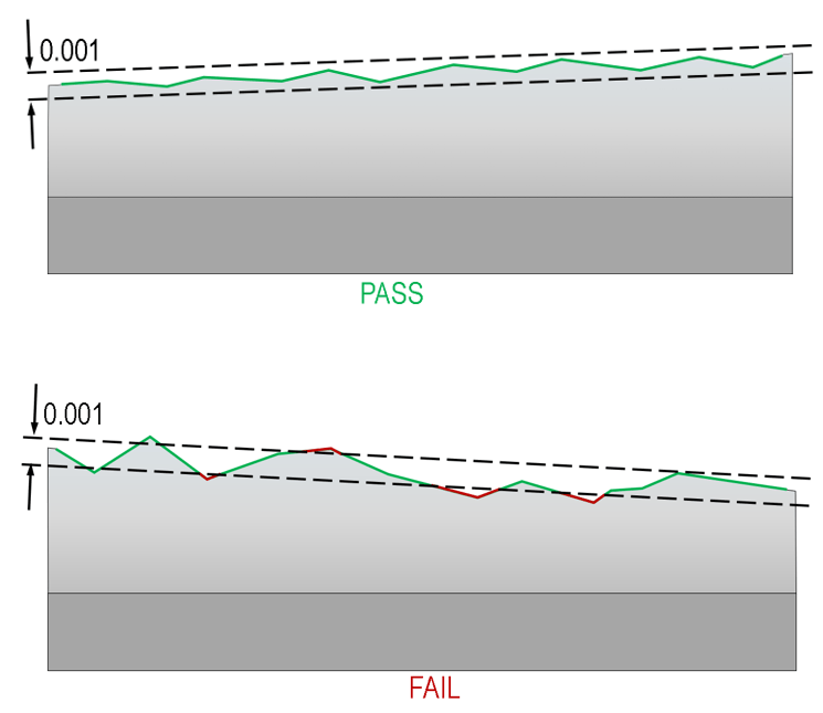
Note that this means only the “highest” and “lowest” points (the greatest deviations from a straight line will ultimately control the reported straightness value, and one or two single outlier points in a measurement can determine if a part passes or fails.
Where can straightness be applied?
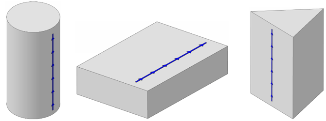
Straightness is perhaps the most widely potentially applicable GD&T control, although in many of the cases where straightness might apply, there are other controls which are more suitable. For instance, flat planes and cylinders have features which could be partially controlled by straightness, but it is often more appropriate functionally to use the more encompassing flatness and cylindricity controls. The choice of control will depend on the functional needs of the part. Below are some examples of feature or axes where a straightness control could be applied:
Amongst the basic form controls (straightness, roundness, flatness & cylindricity), straightness is unique in that it can also apply to an axis, not just a surface. In these situations, the behaviour of the control is slightly different.
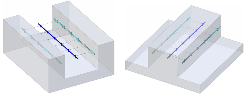
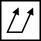
Like flatness, straightness can also apply to a virtual feature – in this case a so-called “median line” or “derived median line” (DML) feature. This can apply to a virtual midline in a gap, or a midline inside of the part material between two parallel surfaces which are nominally straight in some direction. Below are two images showing a derived median line in both a recessed slot and a raised tab. Note that unlike the derived median plane for flatness, the derived median line for straightness need only apply in one direction, so the surface could be curved or irregular in the other orthogonal direction.
Straightness of an axis
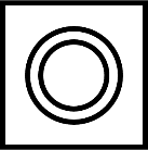
It has been mentioned that straightness can apply to an axis. In this case, the behaviour of the control is quite different – beyond sharing the name and symbol of the surface straightness control, in all other respects the axis control is quite different. On a drawing, the axis control is associated with the feature of size (FOS) of a cross-section of the axis, e.g. in this case the diameter:
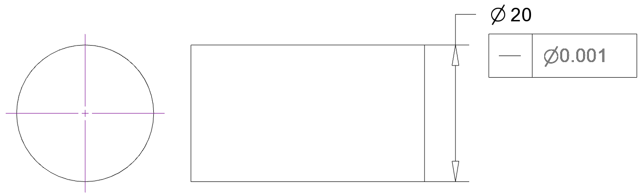
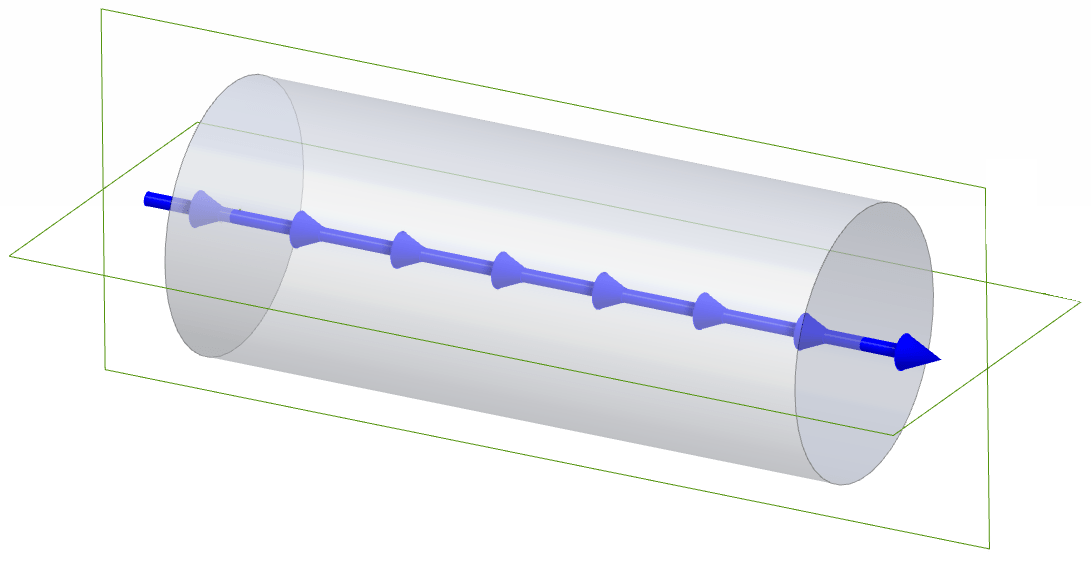
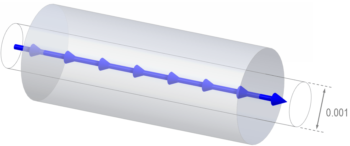
And the tolerance zone is now a cylindrical zone around the axis centreline. The measurement requires a series of 2D cross-sectional measurements, each sweeping around the part, along the length of the axis (the more the better – the ideal case would include an infinite number of cross-sectional measurements). The requirement is then that for each cross-section the measured median point lies within this cylindrical tolerance zone. (The median point is the centre point of the cross-section, so a clear definition is required – ensure that your inspection process has a clear method for locating this point as there is s).
Note that the illustration above shows a cylindrical part, as this is the most geometrically simple, but straightness could be applied to a different extruded profile, e.g. an elliptical profile or any other shape of prism, as long as a definition for the median point is standardised – and of course as long as the axis is nominally straight in the ideal design intent.
What standards apply?
For more details, see ISO 12780, and ASME 14.5-2018, Section 8. Be aware also of the tolerancing classes for straightness and flatness specified by ISO 2768.
Straightness vs flatness
Straightness is often compared to flatness. Where straightness measures follow a one-dimensional trace over a surface in 3D space, flatness scans cover a two-dimensional trace. Generally a flatness control therefore constrains the surface form more than straightness, and flatness cannot apply to, for instance, cylinders or conical tapers, where straightness can.
Note however that the ability of straightness to control an axis is unique; the flatness control does not have an equivalent function to this.
Straightness vs profile of a line
Profile of a line can mimic the straightness constraint when applied to a surface – but be careful, a profile of a line constraint applied relative to datums will also control the absolute position and orientation of the surface. Whereas straightness is an unconstrained, independent form control, profile of a line is a much more stringent constraint – but this may also make it more expensive, and require more complex measuring equipment. Arguably, a straightness constraint as a stand-alone inspection is much more intuitive and straightforward for an engineer reading the prints. Consider what you really need from your inspection process and ensure that your drawings are planned accordingly.
Interested in fast and accurate measurement of precision components with an optical CMM? Try the OmniLux range of coordinate measuring machines.
Overview of GD&T
For an overview of GD&T including the other symbols, please see our practical guide.

Special case: Sphericity