Practical GD&T: Circularity or Roundness Measurement – Basic Concepts
Circularity or roundness of a part in GD&T is defined as the closeness of a cross-section through that part to an ideal circle. Because a circle is a two-dimensional shape, roundness only applies to a two-dimensional profile.
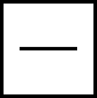
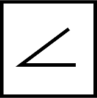
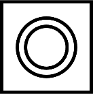
GD&T symbol
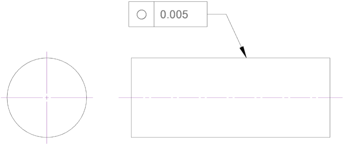
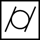
The circularity or roundness symbol used in a feature control frame is shown below. A single number to the right is required and defines the numerical threshold for a pass/fail check. A datum reference is not used in this context.
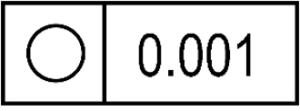
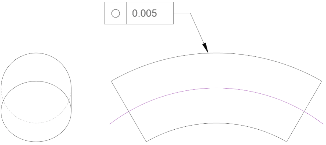
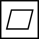
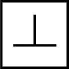
Drawing callout
An example of a roundness callout is shown below:
Note that a roundness measurement is a measure in a 2D plane, so a roundness control may also indicate where this control applies. In the above image, it is at the indicated section of a cylindrical shaft.
On the actual part, this would mean that a cross-sectional profile is measured at that location, and all points must be within the tolerance zone:
The roundness zone can be imagined as two concentric circles, with the difference in their radii being equal to the number given in the call-out. If it is possible to fully contain the measured profile by translating and scaling these concentric circles, the profile is in-tolerance for this inspection check. As shown in the figure below, all measured points on the surface must lie within those two concentric circles; if they do, that is a pass, if not it is a fail.
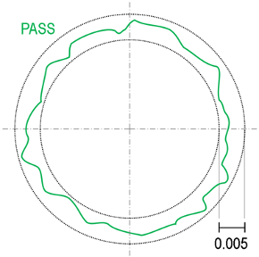
All points within the tolerance bank (the black circles); this is a pass
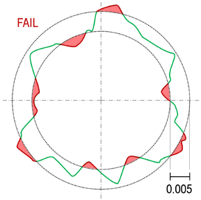
At least one probed point out of tolerance (in red); this is a fail. There is no way to move those circles, or make them larger or smaller by the same amount, and manage to contain the entire profile fully between them.
Is it called roundness or circularity?
The terms roundness and circularity are often used interchangeably in everyday engineering language. The ASME standard uses the term ‘circularity’ but offers ‘roundness’ as an alternative, while the ISO standards exclusively use ‘roundness’.
Where can roundness or circularity be applied?
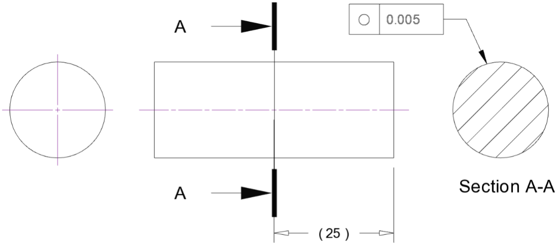
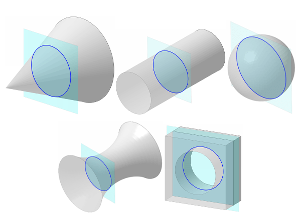
Because it is a 2D measure, roundness can apply to any shape that has at least some region where the cross-section would form a circle – including shafts, balls, cones, and more complex freeform shapes. The surface could be an external or an internal feature – roundness can apply to holes as well as shafts. As long as the profile is rotationally symmetric in some location, roundness may apply. See some examples in this image, showing a blue plane where roundness may apply:
What standards apply to GD&T roundness and circularity?
For more details, see ISO 12181, and ASME 14.5-2018, Section 8. Note that historically roundness was covered by the now-withdrawn ISO 6318.
Roundness vs cylindricity in GD&T
Roundness is a comparison of a measured data set to a best-fit circle, i.e. a two-dimensional shape. A roundness measurement is a property of a circular profile in a given 2D plane. So you can for instance talk about the roundness of, say, a 3D cylinder, but this is not the same as cylindricity, which is measured simultaneously at every point on the surface.
It is common to see an illustration like the below given as an example of roundness; this may lead to the impression that roundness only need be checked once at a random location on the part, but this is not the case. If the inspector only needs to check the part at one single location, that location should be specified. If no location is given for a roundness measurement, it is assumed to apply individually at an infinite number of independent 2D planes across the entire surface and normal to the axis of rotation.
If the above is interpreted to apply to the entire surface, it would only require each individual 2D cross-section to be round – but not necessarily on a common straight axis; a bent shaft could satisfy this requirement, as shown below. Any individual cross-section normal to the axis must be round. But the below could not satisfy a tight cylindricity control. The cylindricity control requires each roundness circular tolerance zone to be on the same straight axis and have the same diameter.
Note that doing a 100% inspection of roundness across a surface like this is, arguably, technically impractical (if not impossible), as it requires an extremely high number of measurements (theoretically infinite). In practice, any true measure would only be an approximation using a finite number of individual roundness scans.
Roundness vs sphericity
The same logic applies to a sphere (e.g. a ball bearing). Any number of roundness measurements can be taken, around the equator or offset, but any one measurement is just a 2D plane and does not describe the full 3D shape. For that a full 3D measure of sphericity is required. This is essentially roundness in 3D, where rather than a common axis, all of the roundness tolerance circles must share a common centre-point in 3D space.
Roundness vs runout
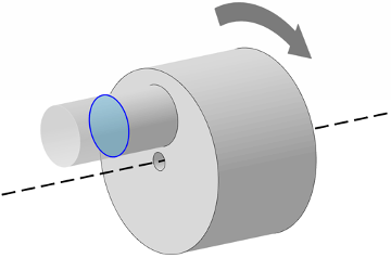
Roundness measures only the local profile of a circle in one 2D plane, without reference to anything else. Runout is a measure relative to some other reference (in this case a rotating axis).
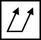
Consider the illustration below, with a roundness control on a secondary shaft (shown in blue), which is offset relative to the main axis of rotation (dashed line). If the part rotates about the dashed axis, the smaller shaft being measured will have a camming motion, regardless of how round it is. This camming motion is called runout and can be large even if the circular profile is perfectly round. Only if the two are concentric, would a part with perfect roundness also have zero run-out.
Roundness vs profile of a line
It is possible to use profile of a line to mimic a roundness call-out. However, it is less intuitive to an engineer viewing the prints and may be taken to imply that the profile design intent isn’t truly circular. Moreover, consider whether you actually want the additional constraint that a profile-of-a-line adds. A roundness requirement alone allows you to have some play in the absolute size of your round feature (which in some cases is acceptable or even desirable – if you don’t care exactly how large the part is – within reason – as long as it is perfectly round). But a profile of a line callout will also constrain the absolute size of the part to the same tolerance as the allowable roundness deviation. This may be desirable – but it may not be (and may make the part difficult or impossible to manufacture!) If the profile is a true circle, and you are ultimately interested in roundness and not size, it is best to use roundness accordingly.
Interested in fast and accurate measurement of precision components with an optical CMM? Try the OmniLux range of coordinate measuring machines.
Overview of GD&T
For an overview of GD&T including the other symbols, please see our practical guide.


Special case: Sphericity