Practical GD&T: Parallelism Measurement – Basic Concepts
Parallelism is a term encountered in geometric dimensioning and tolerancing / geometrical product specifications (GD&T or GPS). It controls a requirement for two features to be geometrically parallel, within a certain acceptable tolerance. As such it is a relative control; no one feature in isolation can be parallel. Parallelism requires some reference feature or geometry, normally a datum.
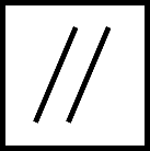
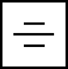
GD&T symbol
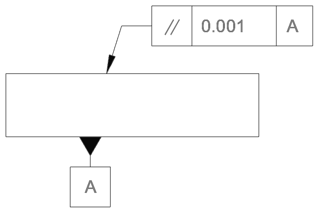
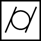
The parallelism control occurs in a feature control frame (FCF) or tolerance frame, as shown below. Note that a parallelism control always requires three elements: 1) the control symbol (two sloping parallel lines), 2) the tolerance (a numerical value in drawing primary units), and 3) a datum reference (denoted by a letter or letters)

Note importantly that the number in that tolerance frame is not an angular value, it is a linear distance – see the example further below in this article.
Drawing callout
As with the other orientation controls, the parallelism tolerance frame does not give all the information required to check the feature. The drawing must also include the datum and, if necessary, the exact way the datum should be measured.
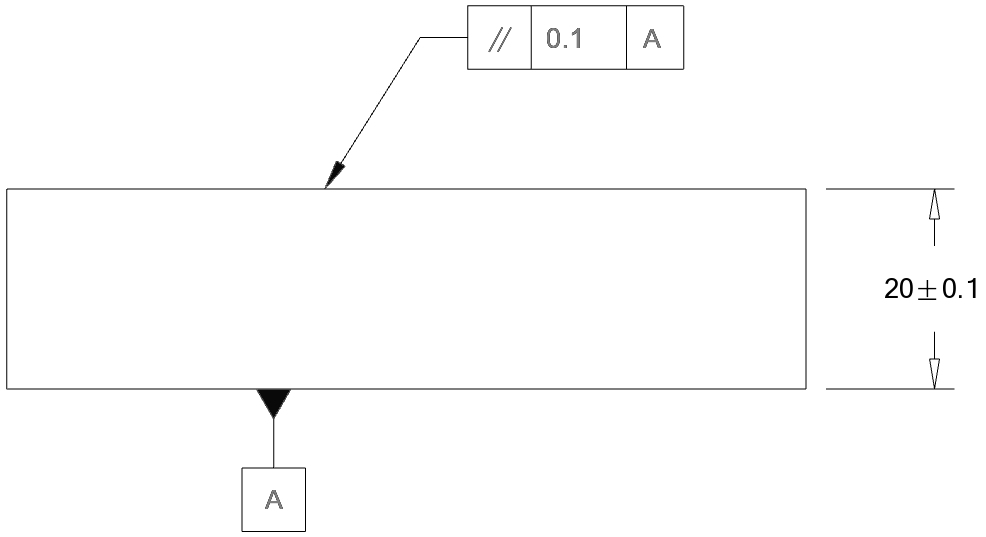
A typical drawing, with both the feature control frame and datum, is shown below.
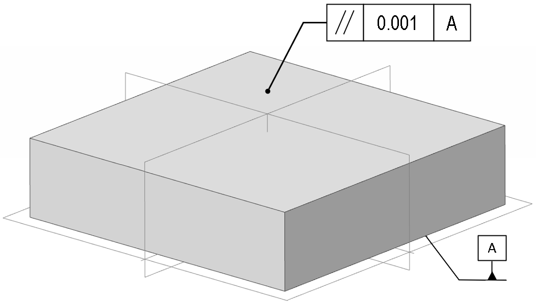
Note that a feature of size (the “thickness” of the block) is not part of the parallelism constraint. You could specify a parallelism constraint without any reference to the length, width, or height of such a block. (When dimensions are given, note that care must be taken to properly understand how they may, or may not, interact with the parallelism constraint – see below for more on that).
The tolerance zone for a parallelism constraint is very similar to a flatness constraint, but it is tied to the orientation of the datum surface. If, for some reason, the datum is not manufactured close to nominal, but is sloping, then the two planes forming the tolerance zone will also be sloping parallel to the datum plane:
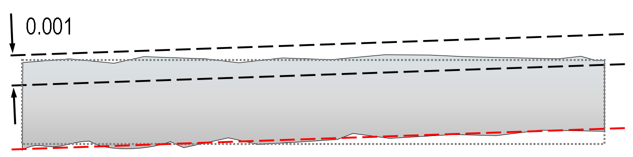
Above: the bottom face (datum A, red line) is significantly deviated from design intent (dotted grey) – this rotates the tolerance zone for the parallelism check – so the top face could be perfectly manufactured, but a shift in the datum might cause the part to fail.
This highlights the importance of correctly inspecting both the datum face and the face controlled by the parallelism constraint. How this is done depends heavily on how the datum plane is defined; if it is a tangent plane constraint, it might be sufficient to rest the datum on a flat surface and measure the height changes on the upper face. But if a different inspection strategy is required, simultaneous measurement of the two opposing faces might be necessary.
Applications
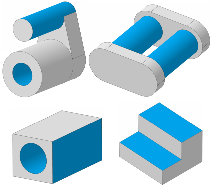
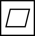
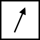
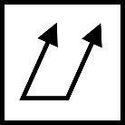
The typical immediate example of parallelism is two parallel planes, as found on for instance gauge blocks. However, parallelism can also apply to axes (e.g. an axis to a flat face, or two axes relative to one another). The images below show a few examples of geometries where parallelism might be applied between features:
Standards
Within the ISO GPS standards family, parallelism has no dedicated standard, but is illustrated with examples in ISO 1101. Parallelism is discussed as a tolerance of orientation within ASME Y14.5.
Parallelism and flatness
For planar faces, at first glance and especially when the datum face is not directly measured, parallelism may appear very similar to a flatness constraint. If a part is simply placed on a datum simulator (e.g. a high-precision granite flat) and then inspected, then the process will be the same. But of course, a part can pass a flatness check in that case if the collected data-points perfectly fit a plane, whatever angle the plane may be, whereas for a parallelism tolerance only one angle – level with the granite face – is acceptable.
Flatness is often tied to parallelism though – a nominally planar surface which is not flat to a certain tolerance can also not pass a parallelism check (or, for that matter, an angularity check or perpendicularity). It is common to see a tighter flatness requirement alongside a more relaxed parallelism tolerance. As already noted, if the datum surface is not planar, then it may be difficult to measure parallelism; in the worst case a ‘rocking’ datum may give ambiguous results – so it is also common to see a flatness on the datum surface. Taking the original cuboid example, a more typical real-life example might be more like the below:
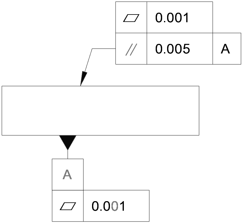
Generally, this only makes sense if the tolerance on the parallelism is greater than on the flatness (although special cases e.g. where the surface is inspected as a tangent plane may override this).
Parallelism and feature-of-size
We noted near the start of the article that specifying parallelism of e.g. a gauge block would not control the thickness of the gauge block. What happens if there is a parallelism constraint and a “feature of size” linear dimension?
The answer is “it depends”. This is one of the simplest examples where the differences between the standards starts to become apparent. Under the ASME interpretation, there is an overriding rule, the “envelope principle” which states that if this block is at its maximum size based on the linear dimension (i.e. 20.1mm), then it has no room left for any positive deviations on the flatness tolerance; it must fall within that maximum ‘envelope’ of size (negative deviations i.e. missing material are permitted).
However, the ISO GPS standards have a fundamental principle of “independence” (see ISO 8015), which means that the flatness is evaluated without respect to any other constraint.
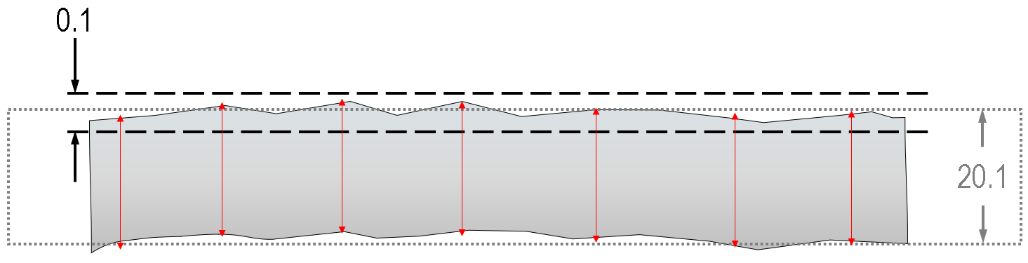
Above: depending on definitions adopted and surface measurements taken, this part could fail inspection by applying an ‘envelope’ principle, or pass with an ‘independency’ principle. Each individual size check (red) is under 20.1, and the flatness is within the 0.1 tolerance, but the part (not to scale) exceeds the 20.1 maximum material envelope.
Note that in both cases (the ASME and ISO standards), it is possible to specify, with notes or modifiers, that these principles do not apply, so a drawing could use either ASME or ISO and in either case pass or fail the above part! It is important in these cases to properly understand which standard a drawing is using and how it is being applied.
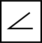
Parallelism vs angularity
In the angularity article, we have discussed how angularity is a more general case of orientation control, and indeed a parallelism control is akin to an angularity tolerance with the special fixed angle of 0°. General practice is to use the parallelism constraint where-ever applicable, but the standards do note the acceptable use of angularity as an alternative.
Parallelism vs profile of a line / profile of a surface
As is the case with many GD&T controls, the constraints provided by a parallelism tolerance would often be ‘bundled’ with a profile-of-a-surface constraint – although the surface profile constraint is often more restrictive, controlling both form and position relative to other features, depending on the datum system it is specified with respect to. The best choice is (as always) dependent on the part requirements in the drawing.
Interested in fast and accurate measurement of precision components with an optical CMM? Try the OmniLux range of coordinate measuring machines.
Overview of GD&T
For an overview of GD&T including the other symbols, please see our practical guide.

Special case: Sphericity