Practical GD&T: Concentricity – Basic Concepts
Mathematically, concentricity is a very simple concept; the centres of two objects with a clearly defined ‘centre’ (e.g. circles or regular polygons) must be at the same location. The challenge in GD&T is that no measured form is ever a perfect circle, a perfect cylinder, etc. This has led to differences in the definition for concentricity. Concentricity is often used as a general term to include co-axiality. Concentricity is no longer a universal symbol, as will be discussed below.
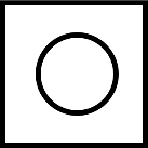
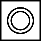
Concentricity GD&T symbol
The symbol for the concentricity control is the same in both the current ISO and former ASME standards; two concentric circles along with, at a minimum, a value for the tolerance, and a reference datum.
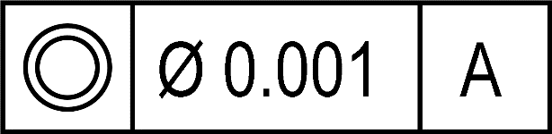
Note that the tolerance zone value will always be specified with the diametric symbol (Ø), because the tolerance zone for a concentricity control will be either a circle, a cylinder or a sphere.
Drawing callout
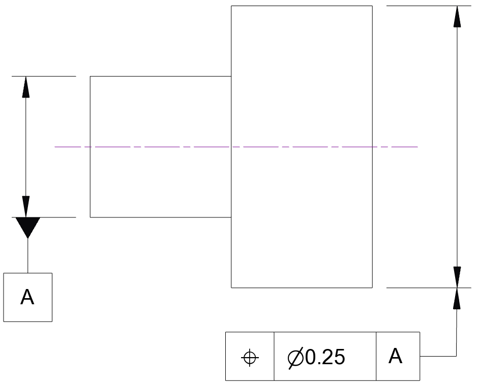
Because of the changes in standards, Various schemes may be encountered for controlling concentricity or co-axiality. For simplicity, we will consider a part with two nominally coaxial cylinders of different dimensions. The smaller radius cylinder we will denote as our datum A and assume in this exercise that this datum is perfectly made (perfect cylindrical form) and all imperfections are on the larger cylinder.
The basic drawing might look like this:
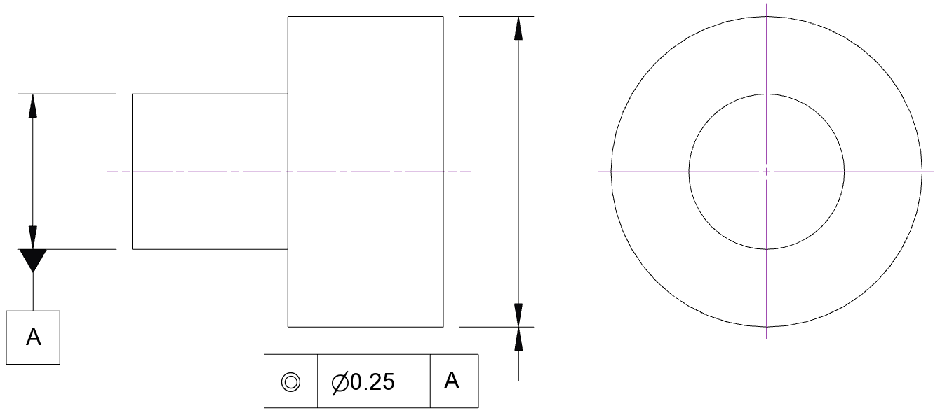
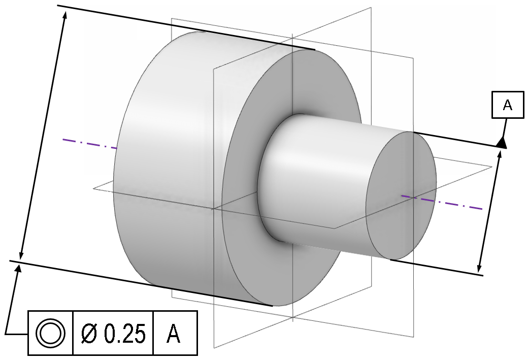
Note a small but important detail: a similar callout for circular runout would be associated with the surface of the larger cylinder, because runout controls the surface profile. Concentricity is concerned with the centre, and the control is associated with a feature of size to indicate it is applied to the axis.
The broad-brushed intention of this callout is simple enough, but the precise implementation differs between standards. In the ISO standard, the tolerance zone is a circle of diameter 0.25; the outer cylinder would be measured around the circumference; the centre of this circle would be determined, and if this centre falls within the tolerance zone, the part passes. For a co-axiality check, this check would need to be passed at all possible locations on the cylinder; (the acronym ‘ACS’ may be encountered, to designate ‘any cross section’). For our hypothetical part with a perfect datum ‘A’ but an imperfect larger cylinder profile, this could look like the below:
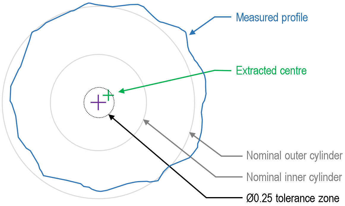
As long as the extracted centre falls inside the tolerance zone, this assessment is a pass on this measurement trace. This means that, depending on the data density, the filtering and algorithm used to determine the centre (and those are all important caveats), it would be possible to have a small outlier in the dataset and still pass the concentricity check:
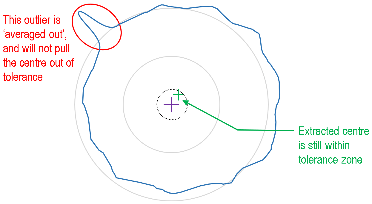
That small outlier zone in the top-left of the profile is not sufficient to pull the measured data-set out of the central tolerance zone. (Note of course it could fail a roundness or cylindricity check, and that might be an important supplementary check alongside a concentricity check).
Now compare the same scenario for the former ASME standard; here the criterion for passing the concentricity check was that for all diametrically opposed points, the median point must lie within the tolerance zone. If any one of these points is outside of the tolerance zone, the check fails. Consider the same outlier profile as before with this alternative definition:
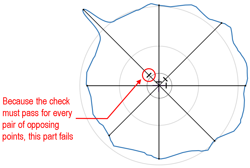
Because the check applies to every diametrically-opposed point pair on the surface, it only takes one pair of points to be out of tolerance to fail the part. The check is essentially evaluating the surface, rather than the centre.
Note that the newer version of the ASME standard has abandoned this definition, and now instead recommends using a <position tolerance> for this same scenario; the control would look like the below, and the behaviour would be much closer to the ISO standard:
As then with the ISO standard, the number of points sampled, filtering or averaging used and the method used to fit that centre-point become critical. Even within the same standard, changing these parameters might change whether a borderline part is a pass or a fail.
This example just serves to illustrate that there are differences between different standards and different versions of standards. Which is correct? Which is best? The answer is it depends on your functional requirements for a given part or assembly. Remember that other GD&T controls are available in your toolkit for tolerancing parts like the one in this example; any combination of cylindricity, roundness, circular runout or total runout might all be appropriate alongside concentricity/position – it depends on exactly what the part needs to do, and why it therefore needs to be the shape it is.
Applications
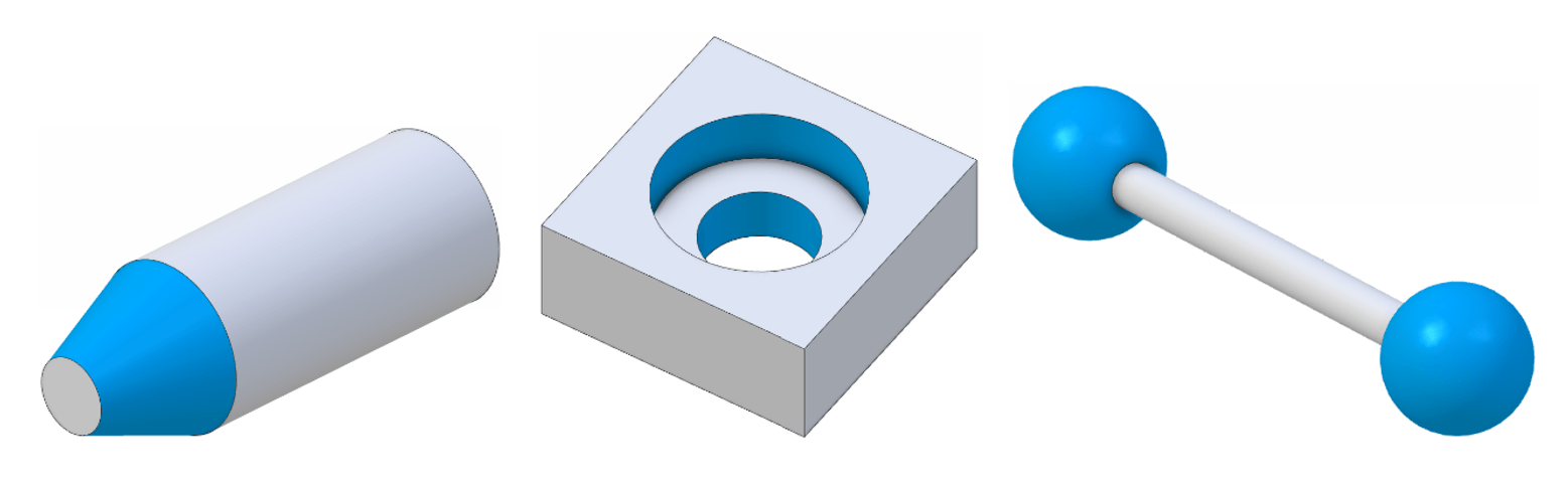
Concentricity can apply to circular, cylindrical, conical, and spherical forms. Technically, mathematically speaking, it could apply to regular polygons or polygonal prisms with a clear and unambiguous definition of a centre, but in practice this could cause confusion, and a <position> control is the better choice (of course, under the newest ASME standard all of these would be position controls anyway).
Standards
It is important to distinguish between the mathematical definition of concentricity, and the specific GD&T control. The mathematical definition of concentricity is not a feature of any standard; it is a fact of mathematical geometry and cannot be ‘withdrawn’. Within both the ISO and ASME standards, the idea of concentricity is repeatedly encountered; e.g. the tolerance zone for circularity consists of two concentric circles. All standards inevitably do and will continue to rely on this geometric definition of concentricity.
The distinction occurs for the GD&T control. Here, the ASME standard has changed position. The 2009 and prior editions still supported the concentricity symbol, but the 2018 symbol has withdrawn that symbol (along with the symmetry control) and advocates the use of position controls instead. Note that the standard has not withdrawn the concept that two features (e.g. two axes) can have a concentric design intent; it simply uses a different form of control for that design intent.
The ISO standard 1101 maintains a symbol for concentricity, with this symbol covering both concentricity and co-axiality.
It is well worth referring to the respective standards to understand the fine detail. The change in the ASME standard from the 2009 to 2018 edition is also a good reminder that standards can change over time; it is important to be aware of older versions, as drawings and parts may be encountered which still use the older standards. It is also important to remember that standards can change in the future, and always check for the most recent updates in case old assumptions are no longer valid.
Interested in fast and accurate measurement of precision components with an optical CMM? Try the OmniLux range of coordinate measuring machines.
Overview of GD&T
For an overview of GD&T including the other symbols, please see our practical guide.

Special case: Sphericity