Practical GD&T: Angularity Measurement – Basic Concepts
Angularity is a control used in a tolerance frame, or feature control frame in GD&T. It can be applied to a feature surface or to an axis and it must be defined relative to a datum – a surface on its own cannot have an angularity with no other reference. Angularity is the deviation from an ideal target angle; unlike perpendicularity and parallelism, which are specific cases of angularity, that angle can be any numerical value.
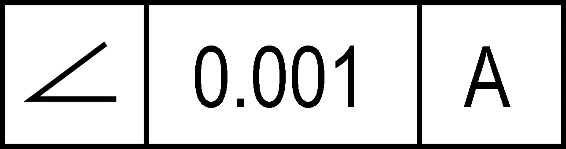
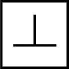
GD&T symbol
A typical angularity callout is shown below. Note that there must always be some reference in the third (right-most) box; here it is a datum, “A”. This is important for the practical application of GD&T – because how you have defined and measured that datum could have a major impact on the angularity control.
Drawing callout
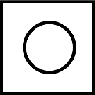
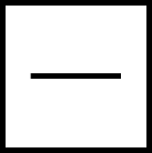
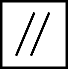
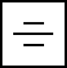
Because an angularity control needs a datum and a nominal ideal angle for the design intent, a drawing cannot just contain the GD&T symbol; for instance, the below would be meaningless:
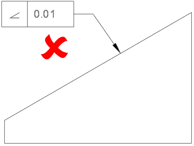
From the drawing, there is no information on what the reference is for this control, and there is no indicated ideal/nominal design intent angle for the slope.
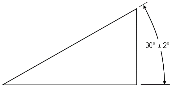
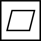
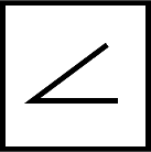
A minimum complete drawing callout would need that additional information, as shown below:
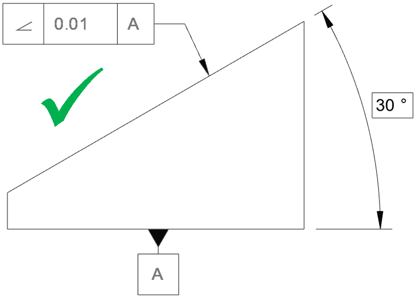
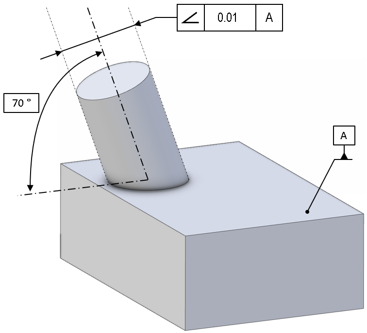
An angularity callout can also be shown within a 3D model view, but again the datum and nominal angle would be required. Note that the nominal angle (here 30°) is a basic dimension.
The units of the tolerance are not angular units; they are units of linear dimension. For example: the above control does not say that your angle needs to be ± 0.01° (or any other angular unit). Rather, it is the size of the tolerance zone – effectively limiting the maximum deviation which can be permitted at any point on the surface or axis. As such, the units of this callout will be the linear distance units being used on the drawing (e.g. millimetres or inches).
For this drawing example, the tolerance zone is a pair of parallel planes at 30°, separated by the tolerance indicated (i.e. 0.01).
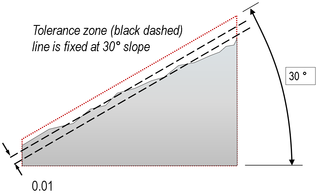
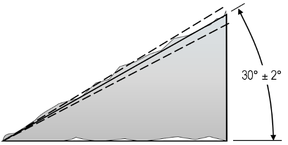
Also important to realise is that the basis for that 30° slope is the bottom face, datum ‘A’. How the angle of this face is measured will determine the angle. Consider the illustration above, modified with irregular features on that lower face:
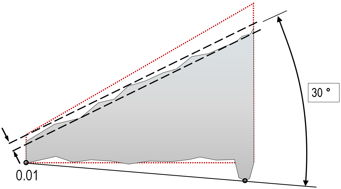
The angle of the lower face is now rotated, which rotates the tolerance zone of the angularity constraint. In fact, the part in this exaggerated illustration would now change from a ‘fail’ previously to a ‘pass’ in this case, based on a change on the datum face, not the sloped face!
This is important; angularity defines the relative angular relationship between two features, and so any change on either feature can change the outcome of the control check.
(The illustration assumes we are using a tangent plane definition for the datum plane; other methods like a least-squares plane fit could easily have resulted in a ‘fail’ instead of a ‘pass’ – it is important to understand how your features are measured, and whether that is the correct choice for your application).
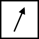
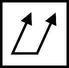
It is important to be aware of the degrees of freedom which an angularity constraint does, and does not, control. Consider the example below:
The design intent may show the projecting pin as leaning in one particular direction, but note that this angularity check would not be sensitive to the direction in which the pin leans; that would require additional constraint (e.g. a second datum).
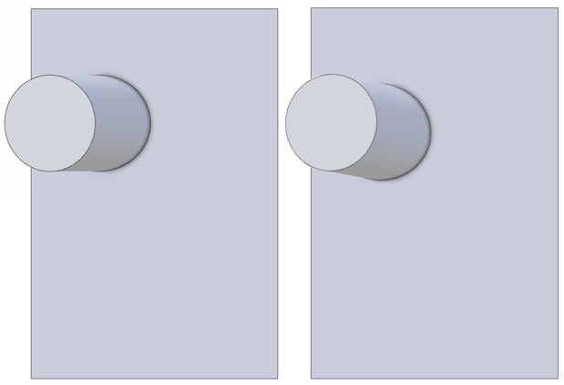
The two cases above, where the pin is rotated about a vertical axis, could both pass an angularity check against the flat plane datum ‘A’.
Applications
Angularity is a very flexible control, but its use is limited, partly because many of the practical cases where angular control needed are the specific cases of 0° and 90° angles, which can be covered by perpendicularity and parallelism.
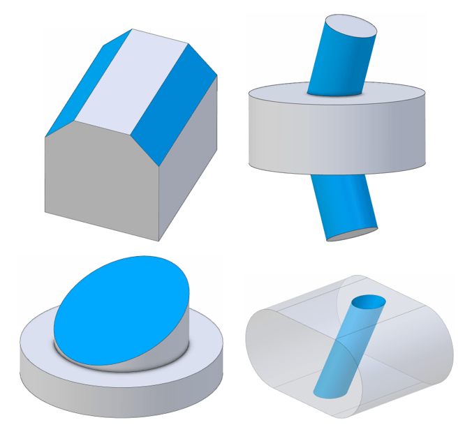
Angularity can apply to positive and negative material features, to actual surfaces and virtual (median plane/line) surfaces, as shown in some of the examples below.
Standards
Angularity is dealt with as an orientation tolerance control within ASME Y14.5, and is still used in the current (2018) revision. Under the ISO standards, Angularity does not have a dedicated standard, and its use is covered under ISO 1101.
Material modifiers
For simplicity, this article has not covered the way that the angularity control can be affected by MMC/MMR or LMC/LMR, but note that these modifiers can apply. Refer to the standards for more details.
Angularity vs perpendicularity / parallelism
It has already been noted that perpendicularity and parallelism are both special cases of angular constraint for the 90° and 0° angular case. This is recognised as acceptable alternate practice within the ASME standard, for instance. Because the concepts of ‘parallel’ and ‘perpendicular’ are generally very accessible and easily recognised on a print, we generally recommend to use these more specific controls where possible. This also allows angularity to be used to more strongly emphasise the distinction when the design intent for an angle is very close to – but not exactly either 0° or 90° (i.e. very subtle slopes).
Angularity vs profile of a line / profile of a surface
The very powerful profile-of-a-line and profile-of-a-surface controls are able to provide many of the constraints that other GD&T controls provide, but note that they are often not interchangeable; for instance if a profile of a surface control has multiple, or different, datums, it will not be identical to an angularity control (e.g. it may not have the same degrees of freedom). Generally, an angularity control is more specific and clearly recognisable on engineering prints.
Angularity vs flatness
At first glance, an angularity constraint might look very similar to the tolerance for a flatness constraint, but note that angularity is tied to the actual realised form of the datum reference. A flatness constraint on a horizontal surface can still pass if the surface is accidentally made vertical! An angularity constraint will not pass in the same circumstances. The tolerance zone for an angularity constraint can be translated to achieve a best-fit (and thus determine pass/fail status), but it cannot be rotated.
Angularity vs angular dimensions with tolerances
A common question when first encountering angularity tolerance frames on a drawing is to ask whether it would be simpler to use an angular dimension, with a plus-minus tolerance. But note that these two are not equivalent. An angular tolerance is less well-defined in the standards, and where attempts are made to give a more definite interpretation, there is still some disagreement. The ASME standard describes two non-parallel planes forming a tolerance zone, while ISO 14405-2 specifically states that each angular check at any location on a surface is independent and there is no parallel constraint between individual locations. If in doubt, use the angularity control, which permits the inclusion of additional datums, modifiers such as tangent plane, etc. This provides the ability to specify exactly what is required in detail.
The angular dimension with a plus-minus tolerance in the above images is ambiguous. There is no one standard for how the tolerance zone should be defined, for instance in the ASME standard (lower image) the tolerance zone is two non-parallel planes, giving zero tolerance near the singularity.
Interested in fast and accurate measurement of precision components with an optical CMM? Try the OmniLux range of coordinate measuring machines.
Overview of GD&T
For an overview of GD&T including the other symbols, please see our practical guide.

Special case: Sphericity